Senior Capstone Project
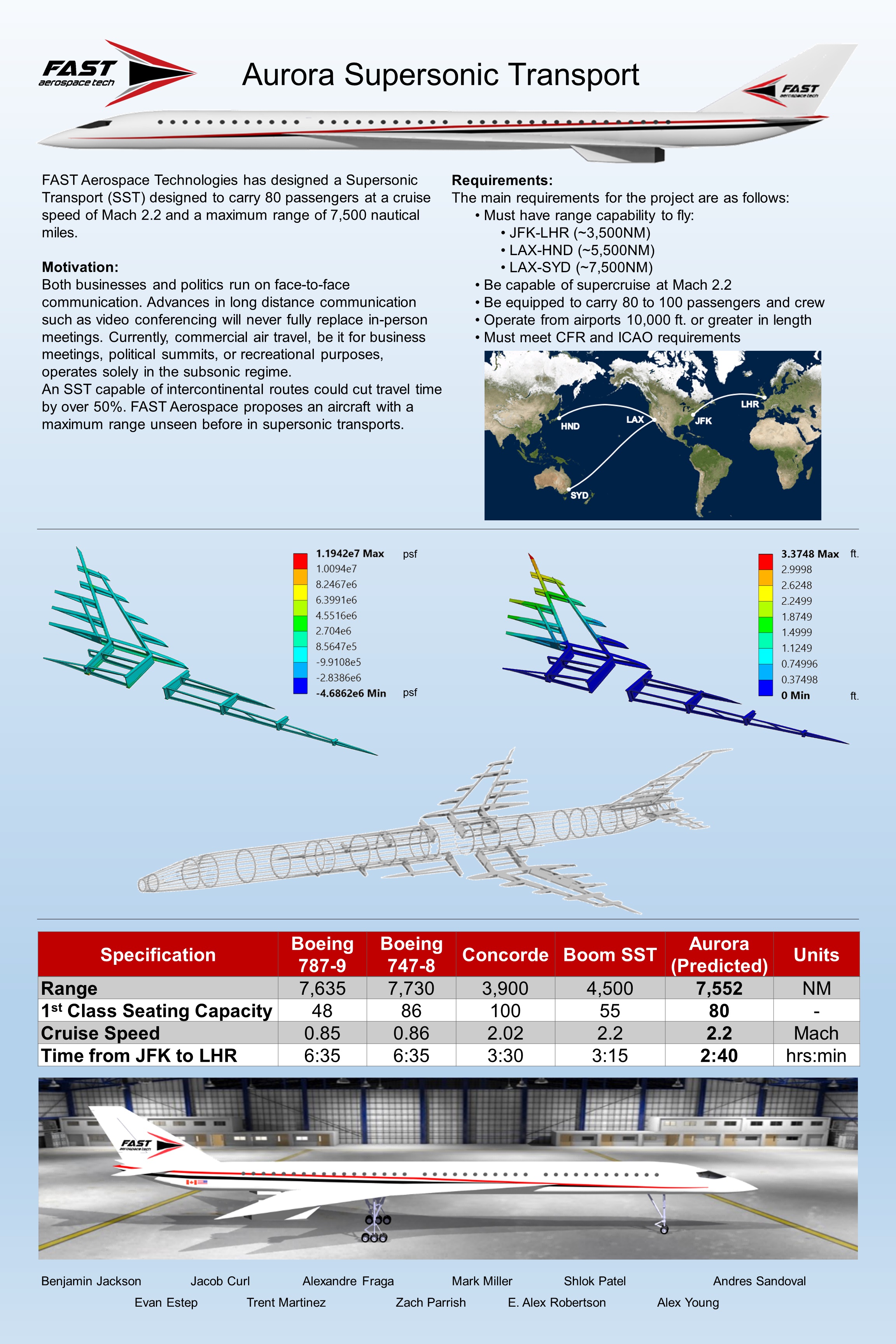
Our senior capstone project entailed designing a supersonic transport capable of traveling 7,500NM at Mach 2.2 with 80 passengers. The aircraft had to meet the initial requirements, as well as the FAA, and ICAO requirements for passenger aircraft.
Our team consisted of 11 engineers split along 6 subsystems; aerodynamics, structures, weight and balance, propulsion, stability and control, and CAD. The projected was separated into two phases; Phase 1 (Fall semester) was the preliminary design and analysis. Phase 2 (Spring semester) consisted of fabrication and wind-tunnel testing of the model.
My role within the project during Phase 1 was aerodynamics. I was tasked with developing the constraint analysis, estimate the CL vs. Alpha and CD vs. Alpha for the wing, strake, empennage, and aircraft, and calculate the takeoff and landing distances. During Phase 2, I was part of the test plan team, where I helped write the test procedures and along with everyone else, the report.
Another significant aspect of our project required us to make a compelling business argument for our design. We had to sell our design to our professors as well as an independent panel of judges from industry as to why our design warranted funding. We created a company name, logo and aircraft name. Apart from being judged on the technical aspects of our design, we were also judged on the professionalism of our presentaton.
One of the reasons I chose Riddle to study engineering was the hands-on nature of their curriculum. This was evident during our capstone project where we designed and built a wind-tunnel model to test our predicted values. Below are some images of our model, wind-tunnel testing, and wind-tunnel results.
Model Fabrication
Our model was 3D printed on a Stratasys Dimension 1200es 3D printer using ABS.
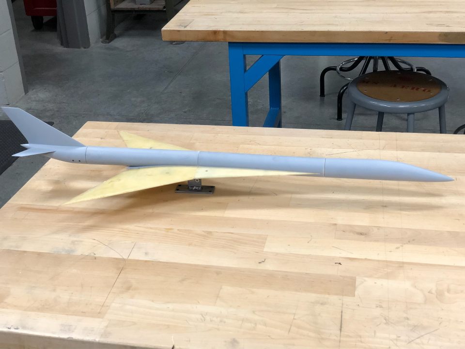
The wings were reinforced with fiberglass resin and were tested structurally by determining the amount of lead shot the wings could support. This limit helped determine the max wind-tunnel speed. If vibrations or flutter were observed before the sturctural limit was reached, then that velocity set the max tunnel speed.
After sanding, the model was painted and covered in tufts to help visualize airflow separation across the aircraft.
Wind-Tunnel Testing
The model was then placed in a closed circuit wind-tunnel with a maximum velocity of 230 ft/s. The model was rotated though -4 to 24 degrees angle of attack at a maximum velocity of 124.6 ft/s.
Black light was used to aid in identifying the direction of tufts and subsequently the airflow. At 0 degrees angle of attack, no change is observed in the tufts.
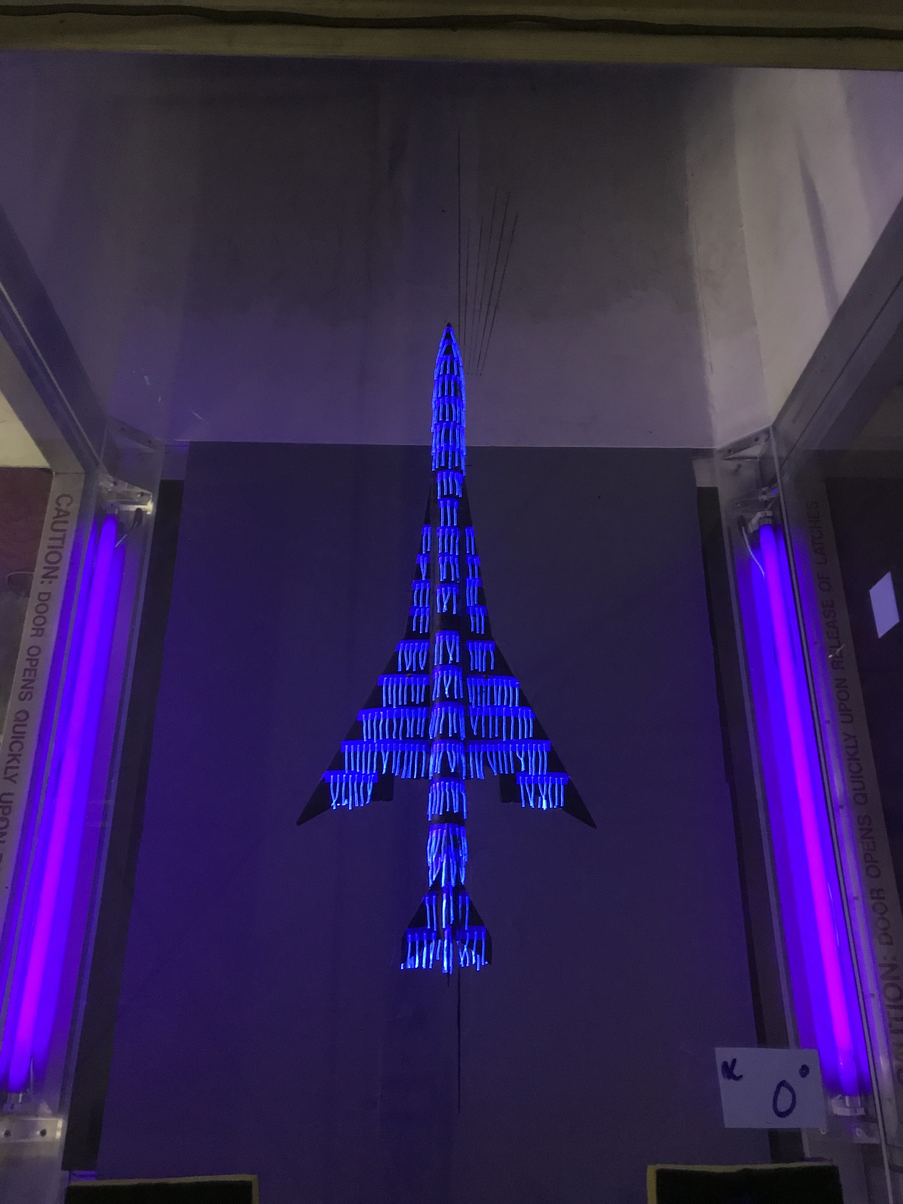
At 24 degrees angle of attack, the tufts along the upper surface curve outward toward the tip of the wing. This is due to a large leading-edge vortex that is generated by the strake and delta wing.

Data
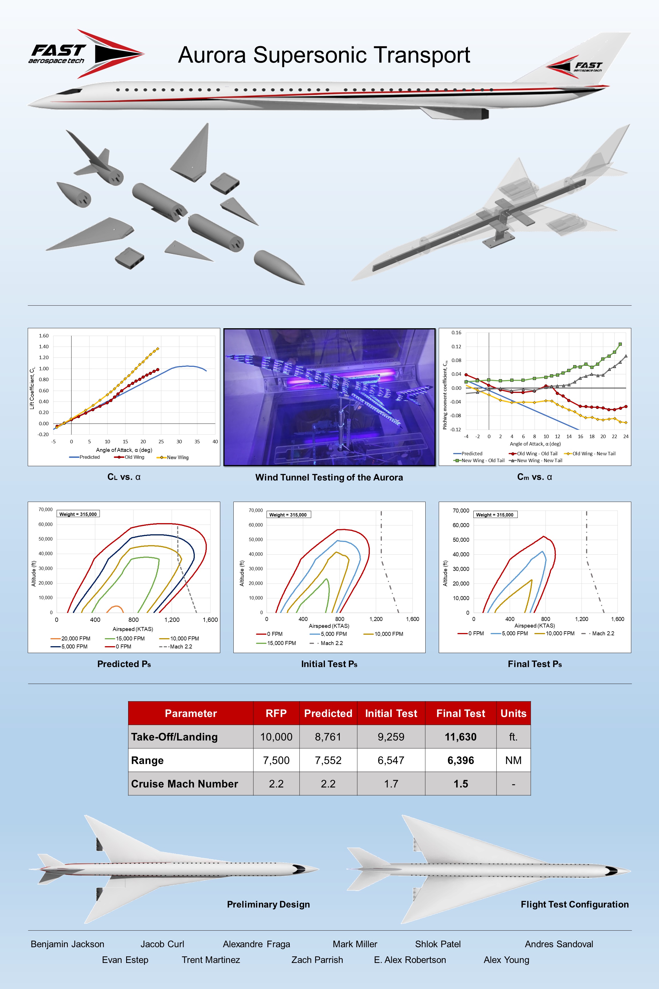
The affects of this vortex are illustrated below, where the lift curve slope (CL vs. Alpha) of the airfoil and wing are plotted together along with the experimental results from the wind-tunnel.
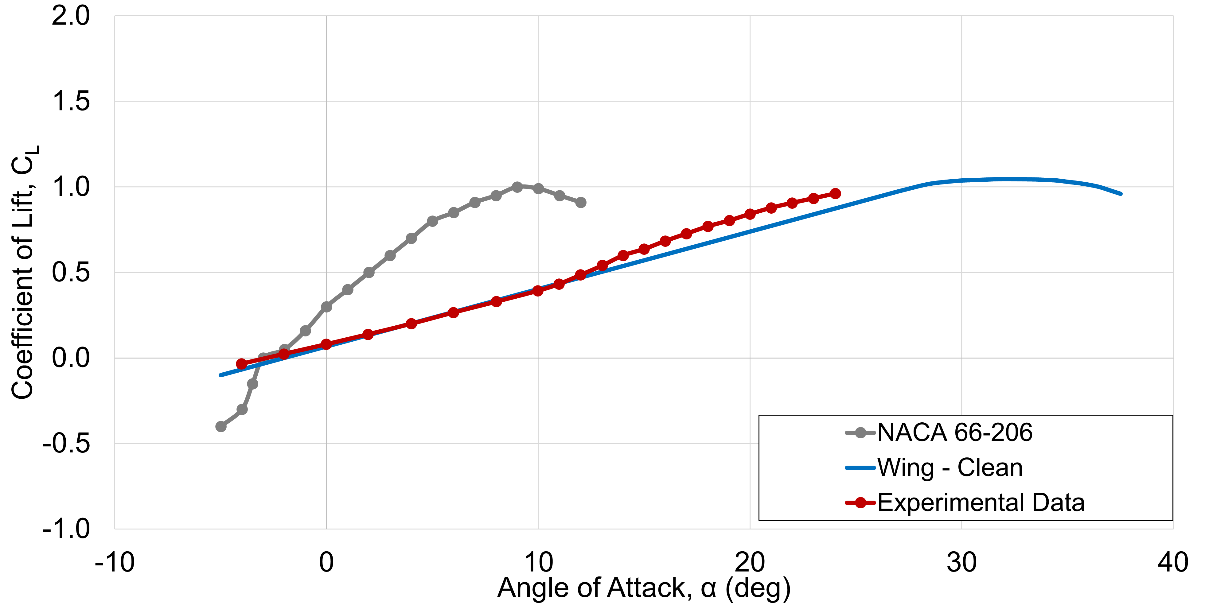
Notice how much later the wing stalls. This is from the leading-edge vortex which generates a low pressure region, delaying stall.
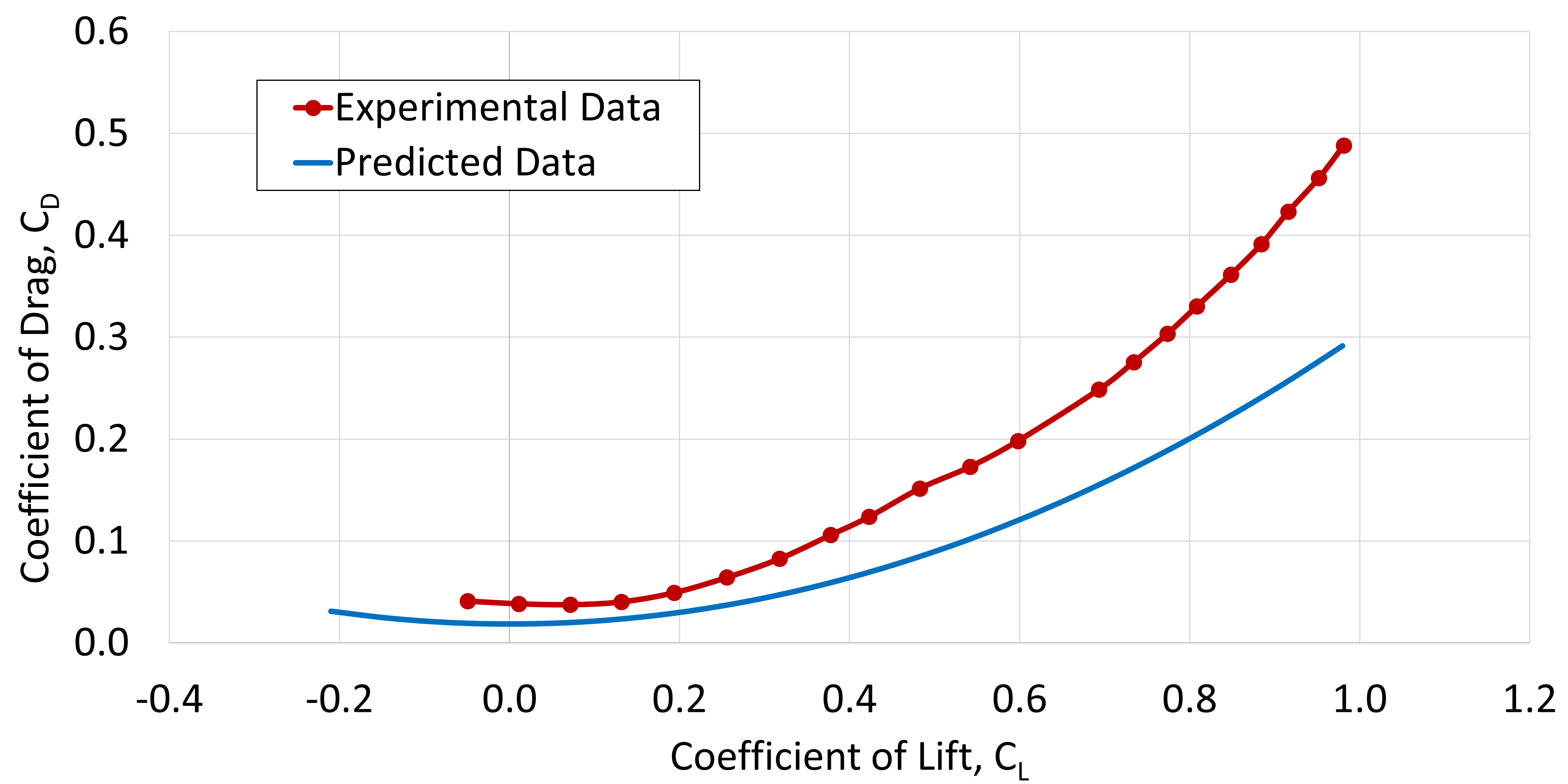
From testing our predicted drag values were a little conservative, which is to be expected because the predictations are based on empirical data from past aircraft. Performing a CFD analysis would have improved our predictions, however it was outside the scope of our project.
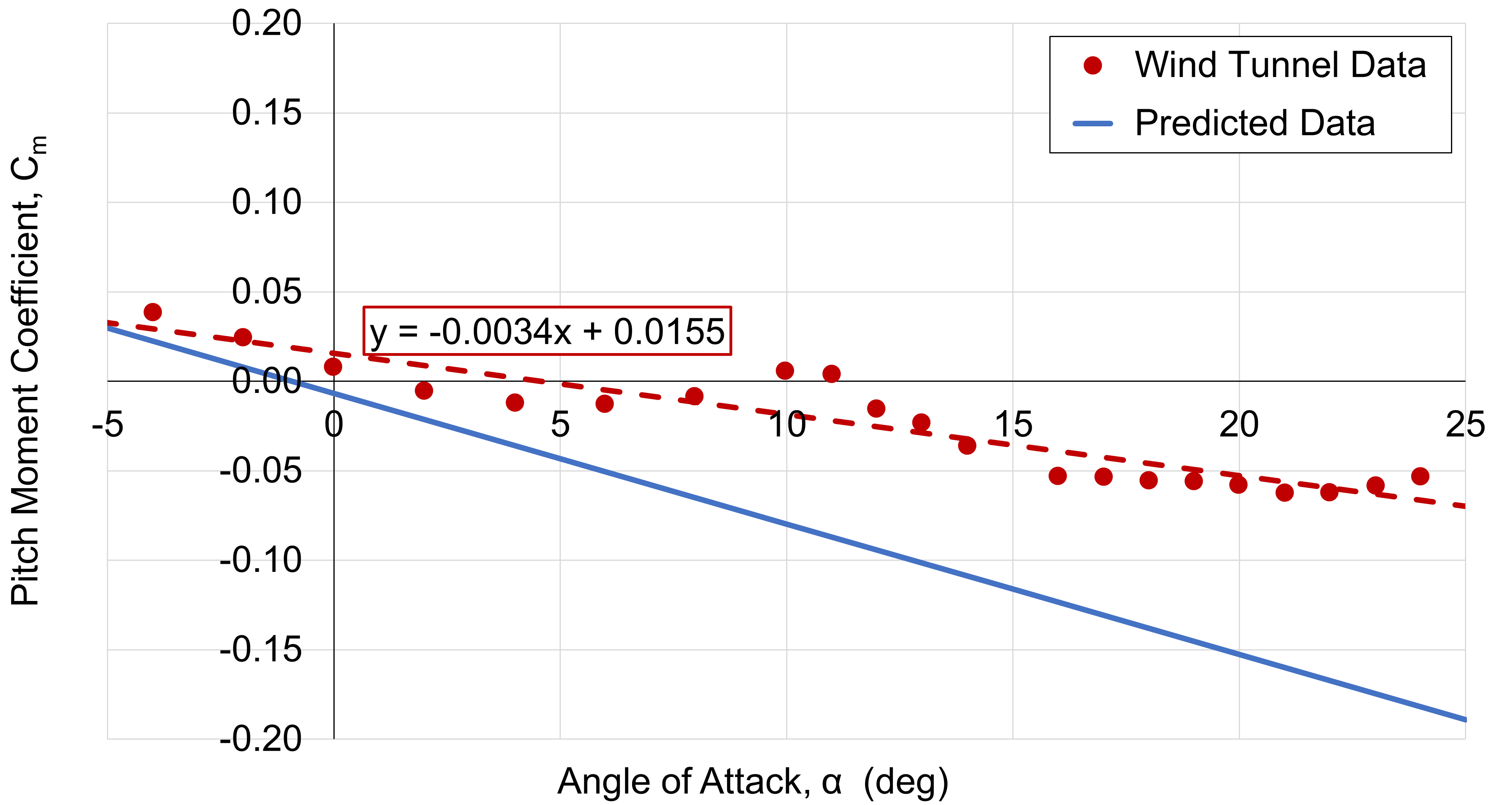
After testing we discovered an instability in our design. Due to the aerodynamic interactions between the strake and delta wing, at 10 degrees AOA, the pitching moment increases to an unstable level. Unfortunately, this instability was during our takeoff roll. To eliminate this we modified the wing to a conventional delta without a strake.
Poster
Our final presentation was in front of a team of industry experts where we presented our concept and the results from our testing. Curiously, one of the judges noted that the instability wouldn’t be a problem with an active flight control system. Unfortunately, we weren’t able to cite this as a solution due to a static stability requirement in all phases of flight.